When water movement stalls, so does everything else. Transfer systems keep frac schedules on track. They regulate truck volume and confirm discharge limits under site permits using real-time telemetry and pressure-rated infrastructure.
What Is Water Transfer Oilfield Infrastructure? Field Definition and Application
In oilfield operations, what is water transfer oilfield infrastructure? It refers to the engineered systems used to move large volumes of water across active job sites. These systems typically connect centralized sources to frac pads, flowback tanks, or injection points.
These systems are built to reduce trucking, increase flow efficiency, and support regulatory compliance in real time.
Key Components of a Water Transfer Oilfield System
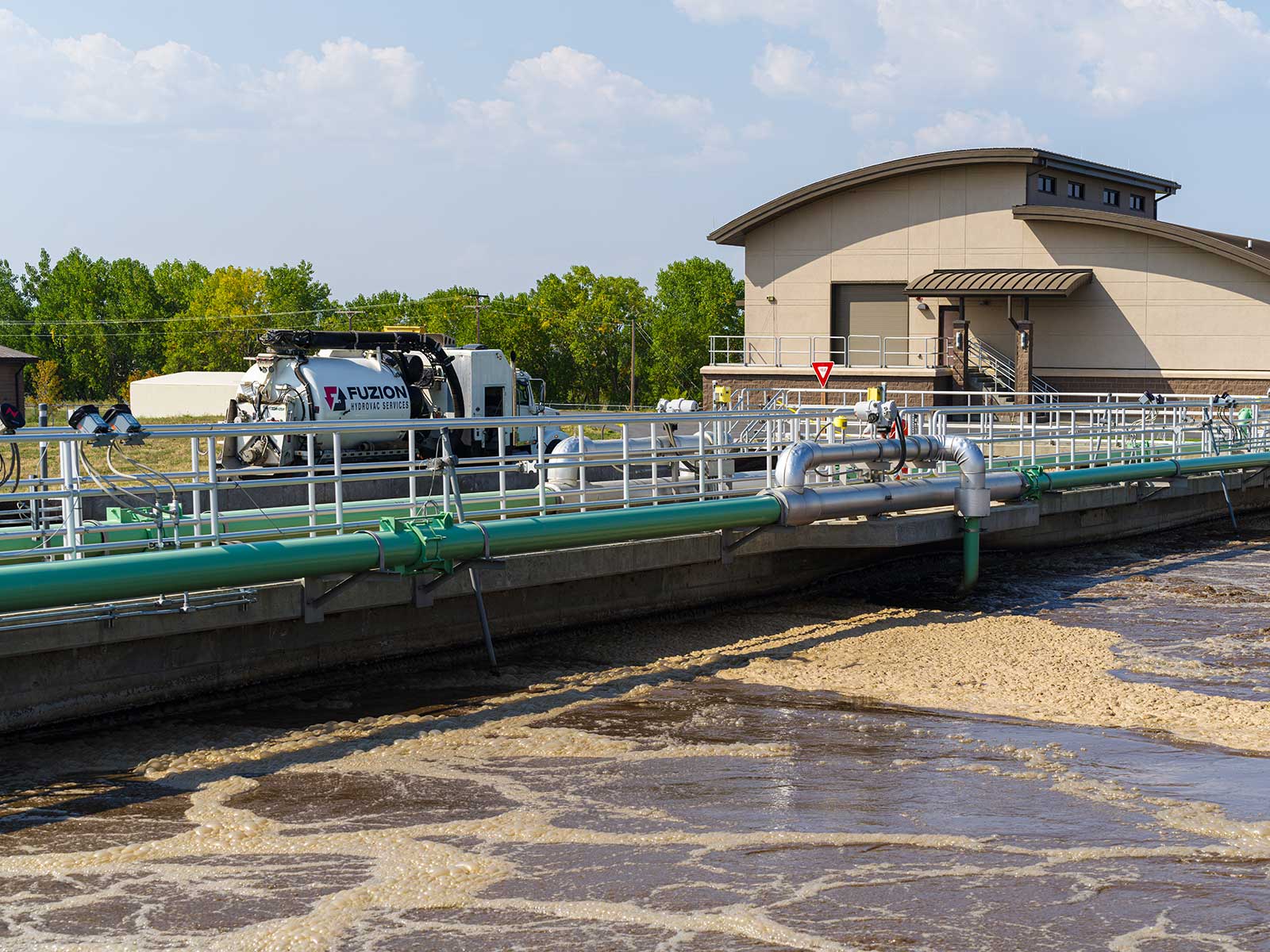
A typical layout includes high-pressure pumps, lay-flat hose, inline manifolds, and—when required—permitted containment berms. Whether the line handles freshwater or treated produced water, the job demands route verification, pressure balancing, and real-time responsiveness.
Field Function and Logistics Impact
A complete water transfer oilfield setup also includes multiple line staging zones across varied terrain. These systems operate continuously to avoid truck-based delays, reduce spill risks, and meet transfer tracking mandates. Once activated, they become the operational backbone of pad-to-pad water logistics.
Transfer Systems vs Hauling Logistics
Trucking remains viable for small-scale or limited-access sites. But in high-volume jobs, vehicle limits, permit loads, and scheduling windows create immediate constraints. Transfer systems sidestep these problems with a fixed infrastructure that
- moves fluid faster,
- more safely, and
- with fewer environmental risks.
For many operators, the advantages of water transfer systems in the oilfield come down to three key factors: higher throughput, reduced risk, and greater compliance certainty. Compared to traditional water hauling methods, the cost savings and performance benefits of water transfer systems become evident almost immediately.
Pump Staging and Throughput Planning
Field teams stage pumps at intake and discharge points and lay hose across miles of terrain. Each pump is sized based on system friction loss, elevation change, and required gallons per minute. Where the layout demands it, booster pumps are deployed mid-line to preserve throughput.
Full-Cycle Layout and Real-Time Monitoring
Understanding what is water transfer oilfield system design means planning for continuous intake, route configuration, pump sizing, and telemetry-based flow control. A transfer system covers the complete cycle—from intake to delivery, with in-line checks throughout.
Intake, Treatment, and Pumping Design
Water is sourced from surface impoundments, mains, or centralized battery tanks. Treatment depends on the end-use. For frac applications, filtration, de-aeration, and chemical dosing may be required. Pumps are staged in series or parallel, with head and flow parameters matched to route demands. Diesel or electric configurations are selected based on pad access and environmental sensitivity.
Delivery Infrastructure and Flow Management
In every water transfer oilfield configuration, pressure control is critical to avoid surge, backflow, and hose failure. As water nears the destination, it may be routed into frac tanks, flowback pits, or disposal manifolds. Field crews monitor flow with pressure gauges and telemetry. Rapid loss of pressure indicates a break or closed valve. Inline cutoff systems are often configured to stop flow automatically under unsafe conditions.
Dual-Flow Jobsites and Volume Balancing
Larger sites handle inbound freshwater and outbound produced water simultaneously. This dual-flow design requires careful sequencing to avoid overflow, pressure conflicts, or treatment backlog. Flow is controlled with
- metering valves
- staging buffers
- and tank-level monitoring,
with digital logs capturing every transfer event.
Engineering Reference Tables for Field Planning
Planning starts with understanding how a water transfer oilfield system handles volume, distance, and pressure across different types of terrain. These reference tables help guide decisions for managing pressure and positioning equipment during water transfer operations.
Hose Diameter vs Flow Rate vs Friction Loss
| Hose Diameter (in) | Max Flow Rate (bbl/min) | Friction Loss (psi/1,000 ft) |
| 4″ | 40 | 12–18 |
| 6″ | 80 | 6–10 |
| 8″ | 120 | 3–5 |
| 10″ | 160 | 2–4 |
- Note: Actual loss depends on elevation change, hose material, and fluid density.
Pump Staging Guidelines by Transfer Distance
| Distance (mi) | Suggested Pump Configuration | Horsepower Range (each) |
| < 1 mi | Single primary | 150–200 HP |
| 1–3 mi | Primary + 1 booster | 200–350 HP |
| 3–5 mi | Primary + 2 boosters | 350–500 HP |
| 5–10 mi | Staged multi-boost | 500–700 HP |
- Staging assumes low elevation gain and 6–8″ hose.
Environmental Controls and Regulatory Expectations
Site conditions and agency rules shape how and where transfer systems operate.
Line Routing and Containment Measures
Hoses must be staged away from protected habitats, creeks, and cultural sites. Where required, berms or secondary containment trays are installed beneath runs. Any crossings over roadways use ramps or subsurface sleeves, depending on the local DOT rules.
Permits, Logs, and Reporting Protocols
Knowing what is water transfer oilfield compliance involves documenting every transfer event with the appropriate permits, pressure tests, and routing logs required for traceable flow operations.
- Regulators may require detailed transfer maps, pressure test results, and daily inspection logs.
- Systems are often audited for setbacks, flagged line locations, and full transfer traceability.
- Records must show compliance with EPA, RRC, and TCEQ standards.
Transfer operations must document pre-line inspections, pressure test results, daily transfer logs, and routing maps. In Texas, operators may also be required to file Form H-11 for injection well data and maintain TCEQ discharge tracking logs. DOT inspections apply for portable tank transfer systems or if any trucks are used to feed the pad mid-cycle.
Water Compatibility and Treatment Inputs
Operators cannot move fluid based on volume alone. Compatibility must be confirmed. Produced water often requires scale inhibitor, pH adjustment, and solids removal before it can be reused or disposed of via pipeline. Improper dosing can cause scale buildup, corrosion, or downhole damage.
Digital Oversight and Automated Protection
Modern transfer systems depend on digital controls to minimize spill risk and maintain audit-ready records.
Telemetry hardware tracks flow rates, pressures, and valve position in real time. When a rupture or leak is detected, alerts are triggered at the control panel and—in some cases—automated shutdowns are initiated. Logs are time-stamped and stored for agency inspection.
These tools also allow teams to run remote diagnostics, identify weak points, and adjust flow settings without sending personnel to the line.
Best Practices for Jobsite Reliability
Consistency in layout and operation reduces risk and downtime. Hoses must be secured with tension relief at anchor points. Elevation changes are mapped in advance to avoid pump overloading. No water transfer oilfield plan is complete without slope calculations, tension relief, and documented emergency routing. And each crew member assigned to transfer work receives site-specific training based on elevation, terrain, and fluid type.
Transfer System Readiness Starts in Planning
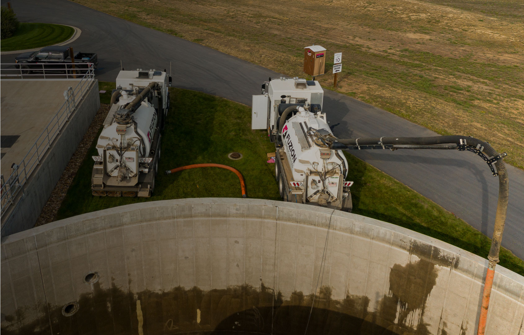
For every water transfer oilfield route, pump staging and route permitting begin long before site mobilization. Weeks before any fluid moves, the route is surveyed, permits are obtained, and staging zones are built.
Pumps and hose arrive only after pressure tests and setback distances are verified. Systems are flushed, tagged, and documented before the line goes live. From the first barrel to the last, every gallon must be accounted for and matched against intake, treatment, and disposal records.
Oilfield Water Transfer Readiness Checklist
Before flow begins, confirm:
- Pump staging zones are permitted and flagged
- Inline gauges and shutoff valves are calibrated
- Hoses are anchored with tension relief
- Digital logs are live and synced
- Spill kits and containment pads are stocked
- Flow path cleared, marked, and inspected
- Chemistry dosing (if applicable) confirmed and logged
Protect Operations with Fuzion’s Water Transfer Solutions
We design, deploy, and manage transfer systems that reduce downtime and meet regulatory standards. Our teams tailor pump staging, line routing, and treatment based on site geography and disposal requirements. Fuzion delivers water transfer oilfield systems that meet timelines and prevent costly flow delays. Contact us today for more information.